
CHALLENGES:
- Calculating the size of a part is time-consuming.
- Need to purchase exact raw material size.
- The additional raw material may lead to scrap.
SOLUTION IN SOLIDWORKS:
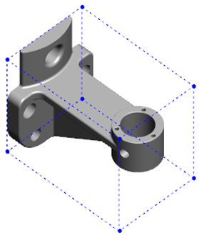
If a part has many faces, create the bounding box after you finish modeling the part.
To create a bounding box for a part and view its properties:
- In a part document, click Insert > Reference Geometry > Bounding Box.
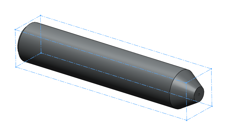
- In the Bounding Box Property Manager, select Best Fit. The orientation of the bounding box is based on the X-Y plane.
To change the reference plane, click Custom Plane.
3. Under Options, select the following:
- Include hidden bodies
- Include surfaces
- Show Preview
If you hide a body in the part, the bounding box automatically updates and only encloses the visible bodies in the model.
4. Click the OK button.
In the FeatureManager design tree, Bounding Box is added after Origin.
You can right-click the bounding box and from the shortcut menu, select Hide, Show, Suppress, or Unsuppress.
To view bounding box properties, hover over Bounding Box in the FeatureManager design tree or click File > Properties > Configuration Specific tab. Values for thickness, width, length, and volume of the bounding box are listed.
BENEFITS:
- Quickly get the bounding box area of the part.
- Exact raw material size information is shown.
- Minimize scrap and reduce cost.

